Optics of X-ray interferometry
《Bonse-Hart X-ray interferometer》
Two difficulties must be overcome in order to construct an interferometer in the X-ray region. One is that X-ray wavelengths are extremely short, and the other is that the refractive indices of any materials are almost unity in the X-ray region.
The wavelength of X-rays is thousands of times shorter than the wavelength of visible light and comparable or smaller than the size of atoms. Although various interferometers are known in the visible light region, they function if the entire interferometer is stable on the wavelength scale. When we attempt to do the same in the X-ray region, we need to stabilize and hold an X-ray interferometer at the atomic level. We face with high barriers to achieve that.
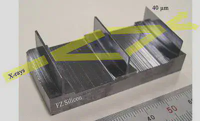
Bonse-Hart X-ray interferometer (Fig. 1), which is cut out from an ingot of Si single crystal monolithically, has been used as a sole hard-X-ray interferometer since its first report in 1962. An interferometric optical configuration corresponding to that of a Mach- Zehnder interferometer is established.
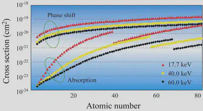
In the 1990s, Prof. Atsushi Momose developed the world-first X-ray phase tomography using this interferometer [1]. Significantly high sensitivity was attained to the materials consisting of light elements, for which conventional X-ray images based on absorption contrast do not generate sufficient contrast. This fact is suggested by Fig. 2, which shows the interaction cross sections of the phase shift and absorption per atom.
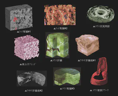
Its excellent sensitivity was demonstrated by the measurements of X-ray phase tomography performed for various samples at synchrotron radiation facilities (KEK-PF and SPring-8). A gallery is given in Fig. 3.
-
[1] A. Momose et al., Nature Medicine 2 (1996) 473-475. DOI:10.1038/nm0496-473 ↩︎
《X-ray Talbot interferometer》
The high sensitivity of X-ray phase imaging and phase tomography is expected to innovate X-ray images. However, the Bonse-Hart X-ray interferometer is basically operated only at synchrotron radiation facilities and does not meet the demand from practical uses (medical diagnosis and non-destructive testing) with a reasonable scan time. Therefore, an X-ray phase imaging technology with an X-ray tube that can be used in laboratories was eagerly desired. So, we proposed X-ray phase imaging with an X-ray Talbot interferometer [2](Fig. 4) to meet this requirement.
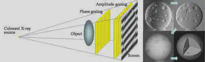
An X-ray Talbot interferometer consists of two transmission gratings, and records and processes X-ray moiré images that are obtained by observing the self-image of the first grating by the Talbot effect through the second grating. X-ray refraction and scattering by a sample is decoded from the deformation of the X-ray moiré images.
Since spatial coherency is needed to cause the Talbot effect, X-ray tubes available at laboratories should have a micro focus. The X-ray flux from a microfocus X-ray tube is limited in general and it takes a long time for measurement. Therefore, further improvement is necessary.
An X-ray Talbot-Lau interferometer shown in Fig. 5 solves this problem. An absorption grating (G0) is installed between a normal X-ray tube and a Talbot interferometer (G1 and G2). One of the slits of G0 is considered as a microfocus X-ray source. Then, a moiré image is formed by the Talbot interferometer downstream. The same applies to the X- rays through the neighbor slit. As shown in Fig. 5, all moiré images are overlaid constructively if the period of G0 are tuned. Thus, an X-ray tube with a normal focus and a high power is available for phase imaging, and practical applications of X-ray phase imaging are expected realistically.
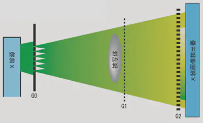
Note that monochromatic X-rays are unnecessary to use an X-ray Talbot interferometer and an X-ray Talbot-Lau interferometer. X-rays from an X-ray tube contain continuous spectra but are available as they are. This is also the case with Figs. 6 and 7 described below. X-ray Talbot and Talbot-Lau interferometers are a type of white-light interferometer in the X-ray region.
-
[2] A. Momose et al., Jpn. J. Appl. Phys. 42 (2003) L866-L868. DOI:10.1143/JJAP.42.L866 ↩︎
《Development of X-ray phase imaging devices》
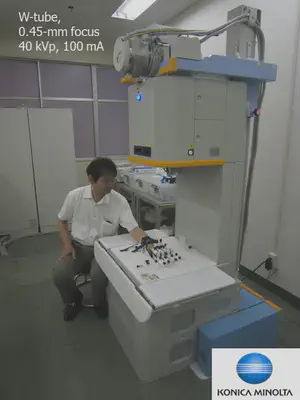
Figure 6 shown a prototype of clinical apparatus for medical diagnosis developed in collaboration with Konica Minolta Medical & Graphic, Inc (installed at Saitama MedialSchool). A Talbot-Lau interferometer is equipped, and it aims at early diagnosis of rheumatoid arthritis, taking advantage of its sensitivity to cartilage [3,4].
-
[3] A. Momose et al., Phil. Trans. R. Soc. A 372 (2014) 20130023. DOI:10.1098/rsta.2013.0023
-
[4] H. Yoshioka et al., Sci. Rep. 10 (2020) 6561. DOI:10.1038/s41598-020-63155-9
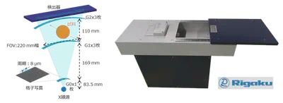
Figure 7 shows a phase scanner device developed in collaboration with Rigaku Co. [5]. In non-destructive testing for industry and security, objects are not always stationary, for example moving on conveyor belts. This device was developed with a future vision of applying X-ray phase imaging to such situations. A desk-sized device has been developed to scan a sample at a speed of 10 mm/s with a field of view of 20 cm.
-
[5] M. Kageyama et al., NDT&E Int. 105 (2019) 19-24. DOI:10.1016/j.ndteint.2019.04.007